Making an old DMX Led Spot "smart"
13.02.2022A while ago I was cleaning up some stuff from my childhood. By doing so I stumbled upon an old led spot, that I haven't used for a long time. I plugged into mains power and everything worked as expected, a reason enough not to throw the led spot away. Because the spot was made for stage events and not for home use, it doesn't feature any fancy WiFi connectivity, so I decided to change this. Luckily the led spot has a DMX connector. DMX is standard for professional stage lighting. It is used for controlling all different kinds of lights (and even lasers). DMX is based on RS485, an RS232 / UART-like protocol for transferring data over long distances. It accomplishes this by sending the signal differentially, avoiding electromagnetic interference. DMX supports 512 channels (from 1 to 512 inclusive). Each channel is set to a value between 0 and 255 inclusive. The controller repeatedly sends these values ordered over the bus to all connected receivers. The concrete channels function is defined by the lighting equipment. These also offer a way to configure a channel offset. Often this is done using a DIP switch. I set my led spot to starting address 1 (offset: 0) and found the following interesting channels in the manual:
| Address | Function |
|---|---|
| 1 | Red |
| 2 | Green |
| 3 | Blue |
| 4 | White |
| 5 | Brightness |
Physically a normal XLR connector is used, the same plugs used for microphones and symmetric audio signals in general. In theory, an XLR audio cable could be used to connect different DMX devices, but this is not encouraged because the wires aren't twisted and the impedance is too low. Therefore special cables for the digital DMX signal are available. The signal is daisy-chained from one light to another. So most DMX lighting equipment offers a DMX input and a DMX output.
Building the Hardware
My goal was to use an ESP2688 as microcontroller to bridge the DMX bus to an HTTP Api accessible over WiFi.
From an earlier project, I had a MAX485 RS485 transmitter IC laying around.
I connected this chip to an XLR Female Socket and to an ESP2688 WEMOS Board, all soldered on a breadboard.
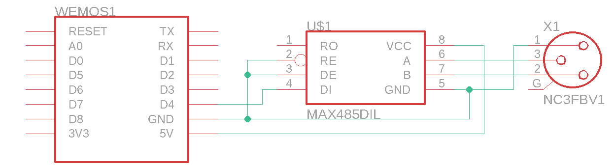 Normally a DMX Interface showed terminate the BUS using a 120 Ohm resistor between the data lines. But the length of my bus is short enough, so I skipped this part.
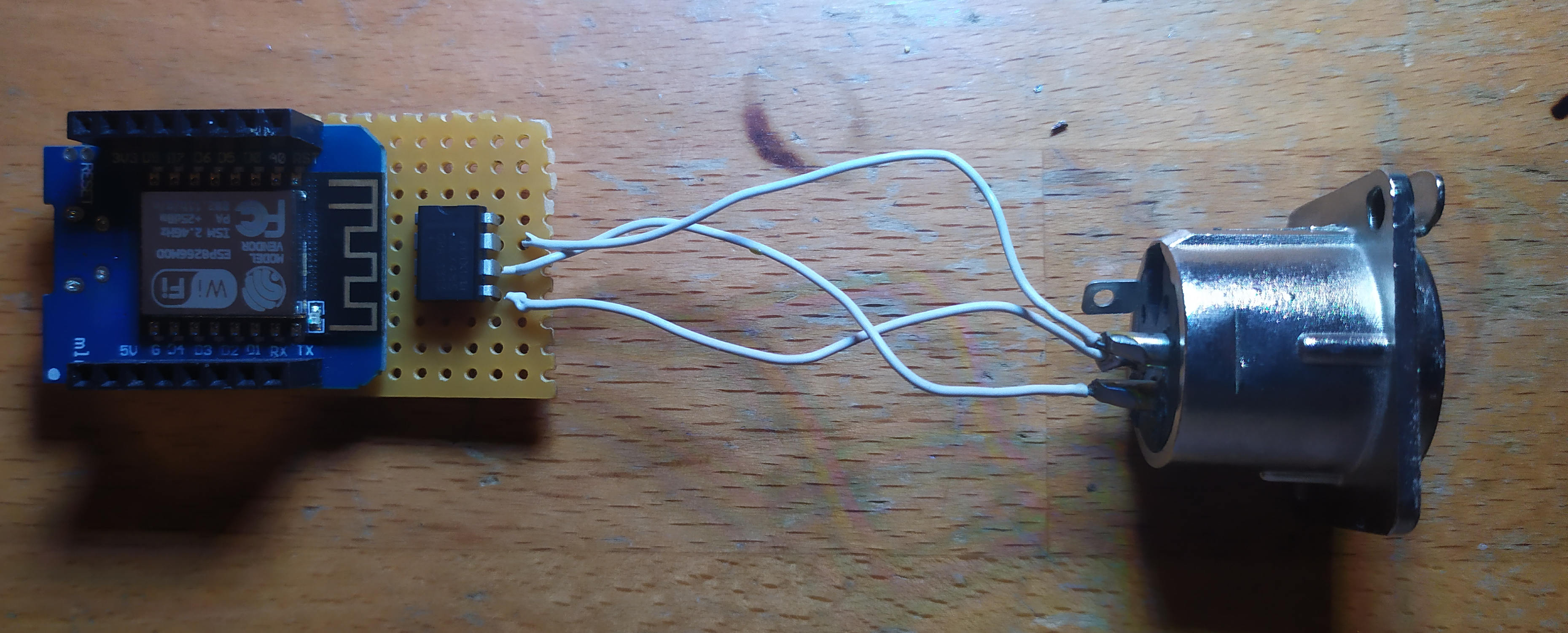
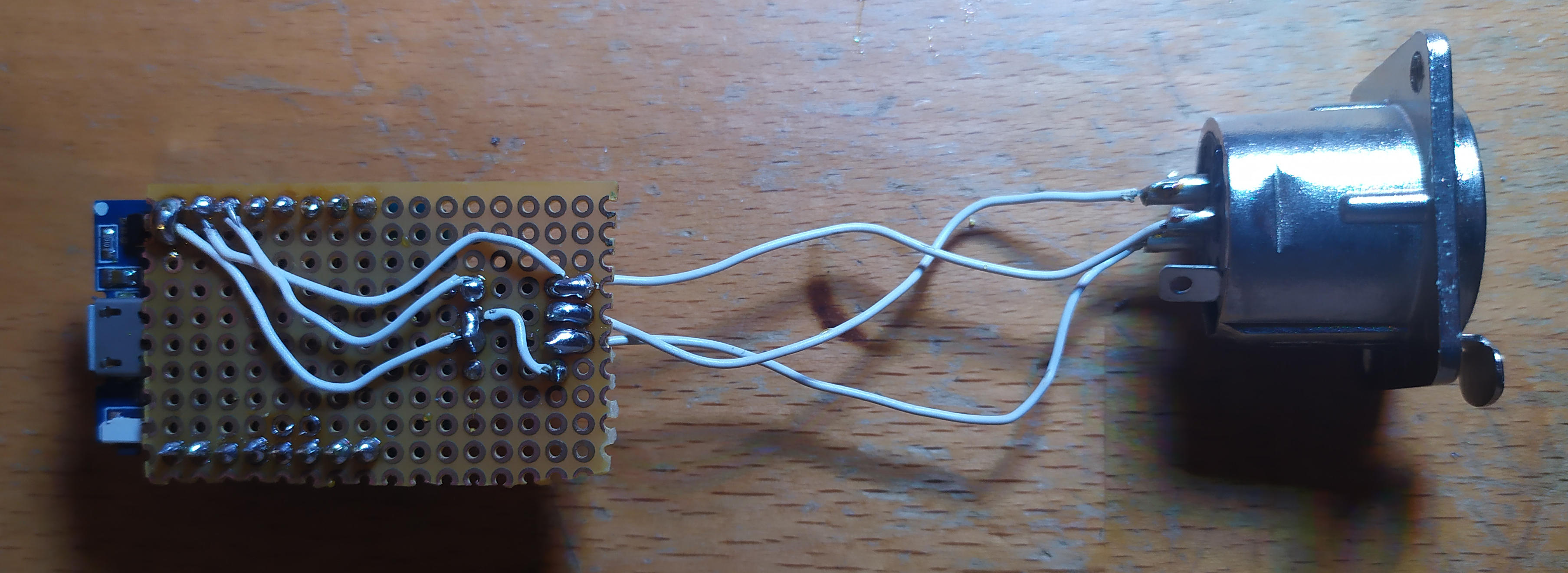
Soldering everything together was straightforward as only 3 components had to be connected.
Programming the ESP 8266
Because the project is not that complicated I used the Arduino Framework instead of the ESP-IDF to develop the Firmware.
When the ESP boot, it first establishes a WiFi connection. Upon success, the HTTP server is configured and started.
Two routes are employed. One for handling DMX value changing requests. And one for providing the HTML of the web interface.
In the main loop, DMX frames are sent continuously. Most of the transmission is handed over to the hardware. The Firmware only has to control the
BREAK period between two frames and has to fill the UART/Serial FIFO with the next DMX channel values.
#include <ESP8266WiFi.h>
#include <ESP8266WebServer.h>

ESP8266WebServer server(80);
uint8_t dmxValues[513];

void handleDMX() {
  int argsCount = server.args();
  for (int i = 0; i < argsCount; i++) {
    int address, value;
    address = server.argName(i).toInt();
    value = server.arg(i).toInt();
    if(value < 0 || value > 255 || address < 1 || address > 512) continue;
    dmxValues[address] = (uint8_t) value;
  }
  server.send(200, "text/plain", "OK");
}

void handleIndex() {
  server.send(200, "text/html",
  "<html>\n"
// ...
  "</html>"
  );
}

void setup() {
  Serial.begin(19200);
  WiFi.begin("YOUR_SSID", "YOUR_PASSWORD");
  while (WiFi.status() != WL_CONNECTED) {
    delay(1000);
  }

  server.on("/", handleIndex);
  server.on("/dmx", handleDMX);
  server.begin();
}

void loop() {
  server.handleClient();
  pinMode(2, OUTPUT);
  // BREAK
  digitalWrite(2, LOW);
  delayMicroseconds(110);
  // MAB
  digitalWrite(2, HIGH);
  delayMicroseconds(4);

  Serial1.begin(250000,  SERIAL_8N2);
  for (int i = 0; i < 513; i++) {
    if (i % 256 == 128) { // Handle some HTTP events, while hardware sends the UART buffer contents async
      server.handleClient();
    }
    Serial1.write(dmxValues[i]);
  }
  Serial1.flush();
}
Building a Web interface
I wanted a way to control the LED spot directly over a Web interface, although an integration into a smart home system like OpenHAB or Home Assistant should be possible. So I build a very minimalistic control panel featuring only a color picker. I found a pretty neat JS library that displays the color picker, so I only had to relay any color changes to the API of the ESP.
<html>
  <head>
    <meta name="viewport" content="width=device-width, initial-scale=0.8" />
    <title>DMX Master 99</title>
    <script src="https://cdn.jsdelivr.net/npm/@jaames/iro@5"></script>
  </head>
  <body>
    <div id="colorPicker"></div>
    <div id="whitePicker" style="margin-top:5px;"></div>
    <script>
      const colorPicker = new iro.ColorPicker("#colorPicker");
      colorPicker.on("color:change", (color) => {
        const { r, g, b, a } = color.rgb;
        fetch(`/dmx?1=${r}&2=${g}&3=${b}&5=255`, { method: "POST" });
      });
      const whitePicker = new iro.ColorPicker("#whitePicker", {
        layout: [
          { component: iro.ui.Slider, options: { sliderType: "value" } },
        ],
      });
      whitePicker.on("color:change", (color) => {
        fetch(`/dmx?4=${Math.round(color.hsv.v * 2.55)}&5=255`, {
          method: "POST",
        });
      });
    </script>
  </body>
</html>